

Updated: Apr 24, 2023
Location: Cambridge, MA + Virtual
Date: Spring 2020
Course Description:
“2.007 is an undergraduate class in the Department of Mechanical Engineering that develops students’ competence and self-confidence as design engineers. It emphasizes the creative design process and the application of physical laws. As is the tradition, the class will end in a final robot competition, in which students compete against each other to see whose robot can win the most total points.”
NOTE: Due to COVID-19, the robot competition was postponed to Spring 2021, where I will get the chance to build the robot that I designed using CAD software over the last couple months.
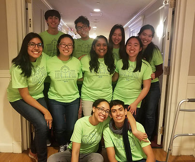
As a junior at MIT studying MechE and Theater, I decided to take 2.007 because I was interning at Milwaukee Tool in Summer 2020 and wanted to experience the design process from start to finish from the perspective of a mechanical engineer (in contrast to Design Researcher, which was my position over the summer). I also wanted to improve my CAD and machining skills, and continue building relationships within my MechE community.
At the beginning of the course, 2.007 teaches us the fundamentals of machining, CAD, and design by guiding us through building a “Mini-Me”: a small two-wheel drive robot that can be used to explore the layout of the game board for the competition and complete some physical challenges.
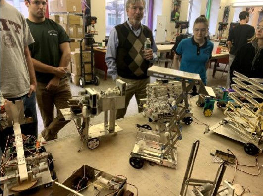
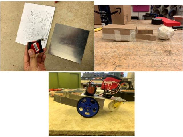

During this time, aside from building the Mini-Me and learning the rules of the game board, and getting more familiar with the machines in Pappalardo, we also were encouraged to start prototyping our own robot.

On March 10th, we were all evacuated from MIT campus.
From March 10th- April 27th, 2.007 was moved virtually and we were asked to focus on the CAD and analysis of our robot.
Thus came: La Poeta

I named my robot La Poeta because at the beginning of 2.007, I felt very nervous about the class's fast-paced and intense nature. I wanted to reassure myself that in no step of the process of designing & building I would have to compromise my identity as a soft-spoken writer, poet, & artist. This is a conflict I have always struggled internally. So, naming my robot La Poeta (which means "The Poet" in Spanish) served as a reminder to always be kind to myself in the learning and growth of the class.
Again, the robots in 2.007 were designed to overcome obstacles on a gameboard while competing with another robot and accumulating points in the process.

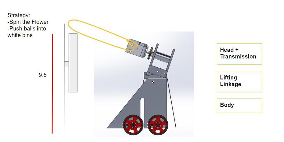
La Poeta's mission, competition-wise, was to focus on spinning the flower spinner and collecting balls, both of which would give me large amount of points & competitive advantage over my opponent during my run on the board.
The Most Critical Module (MCM) of La Poeta is the Head/Transmission + wire that hooks over the flower spinner (shown above). Once lifted, hooked, positioned right along the middle of the spinner, and backed up, there is enough tension on the wire that the head spinning will lead to the flower spinner to do so as well.
Once the Flower Spinner is spun, the game board releases balls on the game board which La Poeta then will proceed push into white bins to gain points.

The head consists of a wire, a head, and a transmission. The wire is most likely airplane wire (or stainless steel wire) that is tied to the head. The head and transmission (which consists of two 97:1 LDO motors) is connected all the way through by an aluminum hex rod. The walls of the transmission and the gears are acrylic, the gears specifically 3D-printed.
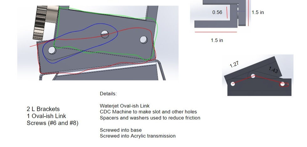
To bring the head/transmission at an angle of ~ 20 degrees, we need a lifting mechanism on La Poeta that is driven by an LDO motor that will lift the whole thing simultaneously. This is achieved by a linkage made of 2 L brackets and an oval link (water-jetted) that are lifted by a sliding mechanism described in the image below.


The chasse of La Poeta will be made of sheet-metal either water-jetted or physically cut using CDC/bandsaw machines to the specific dimensions figured out in this class. It will require a lot of bending, or alternatively, sending the cut sheet metal to the waterjet @ the lab.

As we can see from the free body diagram, we need to make sure that the friction of the wheels are greater than the tension force on the cable. This will be iterated upon during the build in Spring 2021.
This was my first opportunity designing from scratch a rigorous mechanical system of moving parts, and figuring out not only the physical relationships between all the moving parts but also understanding details of the manufacturing process increased my capacity as an engineer.
Shop skills: lathe, CNC, bandsaw, bending
Iterating ideas across mechanical & physical principles. For example, this is a great idea, but how will the way I fasten it affect it's performance? Is there another way I can bend this metal that will serve it a better purpose?
CAD skills (reflections, building systems, restricting degrees of freedom)
Critically assessing dimensions to maintain under 16 X 16 X 16 in restriction, as well as manipulating shape to create a pleasing aesthetic while maintaining center of mass at an optimal location
At the 2.007 awards ceremony, La Poeta received the Creative Spirit award (given by my lab mentor) for its commitment to the heart & effort & spirit of being a creative, meaningful engineer.
Updated: Sep 1, 2023
Location: Cambridge, MA
Date: Fall 2019
The class 2.671, Measurement and Instrumentation, tasked me in creating a technical research project from inception to validation. Because I recently had learned to play the ukulele, I decided to use this opportunity to understand why the online ukulele community recommended strumming where the body met the neck, AKA "the sweet spot". I learned fundamentals of signal processing, uncertainty, and structured technical communication.
What I Learned:
how to engage in a research & poster presentation
how to make information accessible for varying degrees of familiarity with the subject
how to design visuals to express technical information
the importance of calculating uncertainty & engaging critically with data
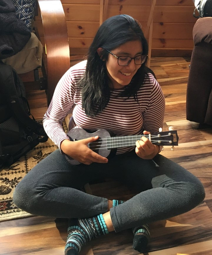
As I mentioned, I had been trying for a while to understand where along the ukulele I could obtain "best" sound. I decided to dedicate my research project to the understanding of this - leading me down a path of understanding timbre, signal processing, fourier transforms, and ultimately the spectrum of sound that could be found within the palette of a ukulele.
Guided by my professor and a plethora of sensors at my disposal and a curiosity about the science behind a musical object I loved very much, I proceeded to draft some tests around the ukulele.
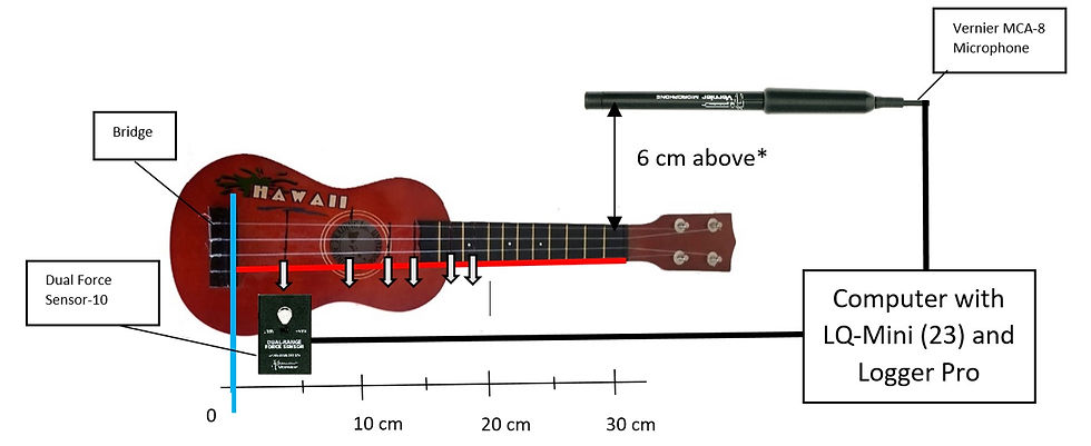
The experimental set-up’s main purpose was to facilitate the collection of sound. The sensors used:
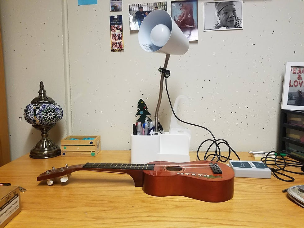
Vernier MCA-8. This microphone, pictured as attached to the “white lamp” in the picture, captured the sound of the ukulele as the DFS plucked it. It was held to the lamp by tape and at an angle of approximately 45 degrees from the table.
Vernier DFS-10. The Dual-Range Force sensor was used to monitor the force used to pull the string during every measurement. To mimic the reality of plucking a string, a screw held a guitar pick inside the DFS as shown:
Vernier LQ-Mini 23: Connected both the DFS and MCA to Logger Pro, software that analyzes input data.
Ukulele: The ukulele was marked at 6 plucking points along the A string (440 Hz fundamental frequency) at given distances the bridge, shown as white arrows in Fig 4.
o 1: 4.0 cm
o 2: 9.2 cm
o 3: 12.5 cm
o 4: 14.6 cm
o 5: 17.7 cm
o 6: 20.0 cm
These values were chosen due to their prevalence as common playing points in the ukulele playing community. Point 1 is located very close to the bridge, its timbre often described as “tight” in contrast to Point 2, which is above the sound hole and described as “round”, “full”, and “loud” sound. The “sweet spot”, a special point in the ukulele-playing community, is found at Point 5, which is the point at which the ukulele’s body meets the neck.
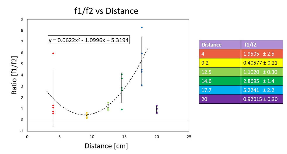
To determine differences in timbre along the body of the ukulele, the main concept analyzed was the intensity of harmonics and their ratios. The fundamental frequency of the A string on an ukulele is 440 Hz [Figure 9], and the second harmonic is about 870 Hz. However, as we can observe in Figure 9, the third, fourth, and fifth harmonic are less than 10% of the intensity of the first and second harmonic. Thus, in this analysis only the first and second harmonic are taken into account to characterize the timbre.

To more accurately understand the intensity of each harmonic, the area of each peak was calculated using integrals, instead of solely relying on the peak’s magnitude. Solely relying on the peak’s magnitude initially led to large uncertainties, due to the MCA Microphone’s limited resolution as well as the DFS’s precision in applying the same force at each pluck.
A parabolic relationship between the ratios of f1 and f2 were found along the ukulele, creating the model for a "spectrum of timbre". The largest ratio is found 17.7 cm from the bridge, where the "sweet spot" is found.
In Summary:
This was my first technical research project! Inspired by my curiosity around ukulele strumming, I created a research project to validate the "sweet" spot along the instrument's body. My results confirmed the existence of the "sweet spot" and produced a spectrum of timbre using the ratio of harmonics at specified locations. I presented my results through a formal presentation, a poster session, and a final paper. The guidance from my professors encouraged me to explore the nuances of my results,
Attached is my final paper, the final deliverable for the class which includes more technical details on the matter.